

No fasteners, no adhesives, fewer components and simplified assembly – that’s the beauty of ultrasonic welding. A proven technique for joining plastic parts, it’s fast, cost-effective and reliable. However, as with any manufacturing process, getting the best from it means designing appropriately.
In the paragraphs below we’ll share some advice on ultrasonic welding of plastic parts. Consider these your ultrasonic welding plastic part design guidelines.
Ultrasonic Welding Basics
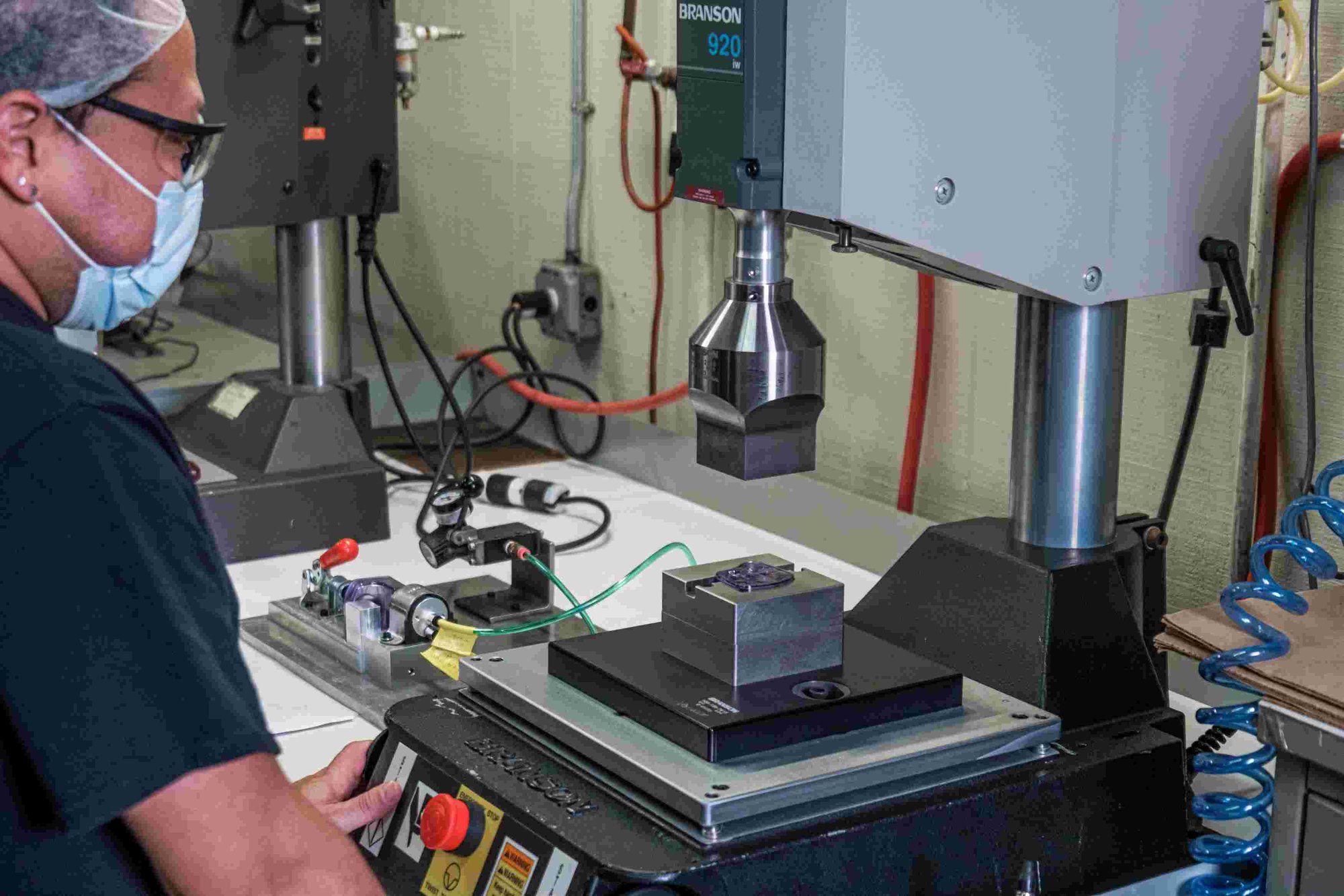
Ultrasonic welding, also referred to as 'sonic welding', uses friction to heat plastics to a temperature high enough that they’ll bond together. This frictional heat is applied through high speed vibration generated in a sonotrode and delivered by a welding “horn.”
Sonic welding machines look similar to spot or resistance welders. A horn pushes against the parts being joined, applying pressure and energy until they fuse together. With modern industrial controls it’s a fast and repeatable process.
When and Why to Use Ultrasonic Welding
Consider sonic welding whenever the design calls for joining separate plastic pieces. One common reason is because it’s not feasible to mold the pieces as one unitary part. Another is that the pieces must be assembled around another part or parts. (Think motor housings or enclosures.)
Sonic welding can simplify part design. There’s no need for large flat areas or holes and it’s possible to create hermetically tight enclosures. By eliminating fasteners it reduces piece count and weight, saving time, money and factory space. It’s also cleaner than adhesives with none of the mixing, storing and dispensing challenges.
Ultrasonic Welding for Plastic Part Design
To use ultrasonic welding in assembly plastic parts must be designed appropriately. This means considering both the materials and the joint design.
Review common materials and their effectiveness in different sonic welding applications with this free guide.
Material Considerations
Ultrasonic plastic welding works best on plastics that soften gradually over a temperature range. Typically these are thermoplastic materials with an amorphous structure. Their melting behavior is characterized by a “glass transition temperature” or Tg.
Among the easiest plastics to weld ultrasonically are polyphenylene oxide (PPO) and acrylonitrile butadiene styrene (ABS). In contrast, a semi-crystalline structure makes polyvinyl chloride (PVC), cellulose acetate (CA/B/P) and polyolefin materials difficult.
Dissimilar Plastics
The easiest situation is where parts being joined are molded from the same material. At the other end of the spectrum are assemblies where the component parts are molded from plastics with different properties. (Note that semi-crystalline plastics can in general only be welded to themselves.)
Gauging the weldability of dissimilar thermoplastic materials entails considering Tg, chemical compatibility and melt flow index (MFI).
As a rule, the Tg of two dissimilar plastics should be within 40°F for them to fuse successfully.
Chemical compatibility is a complex topic that comes down to the proportions of radicals within the polymers. Compatibility exists when these values are similar within the two materials.
Melt Flow Index is a measure of how easily a plastic flows as it transitions to a liquid state. For any given material the MFI can be found in the manufacturers literature and is given as a single number. For best results plastics being joined should have similar MFI’s.
Joint Design
In ultrasonic plastic welding it’s important to focus the energy in as small a region as possible. This means incorporating an “energy director” into your sonic welding plastic design.
An energy director is a raised region with a triangular cross-section. The triangle tip is pressed against the mating plastic part and ultrasonic energy applied. With friction occurring over a very small area the local temperature rises quickly. As it goes through the Tg melting begins and the plastic components join together.
An energy director design is used with almost all sonic welding plastic part designs, except when the materials are semi-crystalline. As these have a narrow glass transition temperature range they tend to move quickly into a liquid state rather than the “gummy-ness” typical of amorphous plastics. To address this, such parts are designed with shear joints. Shear joints are formed when the side walls of opposing parts are pushed together.
Common Types of Energy Director Designs
The main types of energy director designs are:
1. Butt Joint
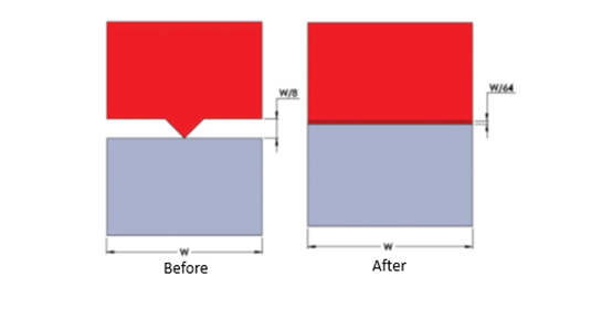
Here one surface is flat while the other has the triangle shape. Keeping the triangle point as sharp as possible maximizes energy transfer.
2. Step Joint
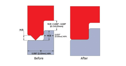
The mating surfaces have a stepped design that minimizes lateral movement while the triangle point presses against a flat surface. (This simplifies part location for assembly.)
3. Tongue and Groove
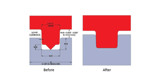
The energy director is on a raised tongue that fits into a groove in the mating part. This provides good alignment of the two parts and minimizes flash.
4. Criss-Cross
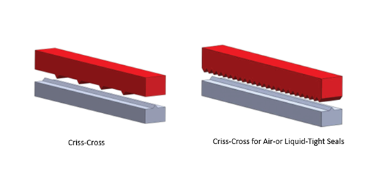
Both surfaces have energy directors but are aligned perpendicular to one another. This yields stronger welds but can also produce a lot of flash. To achieve an air-tight seal configure the crossing energy directors as a sawtooth.
5. Textured Surface
Texturing the non-energy director surface is an effective way of increasing weld strength.
6. Perpendicular
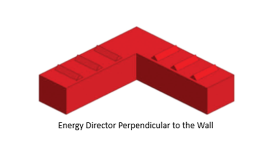
In this design the energy directors run perpendicular to rather than parallel with the joint faces. This reduces flash.
7. Interrupted
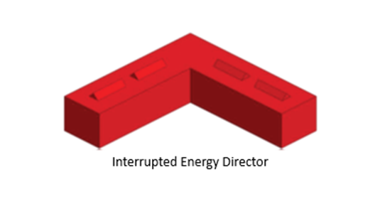
Here energy directors are kept short. This reduces the energy needed to make the weld.
8. Chisel
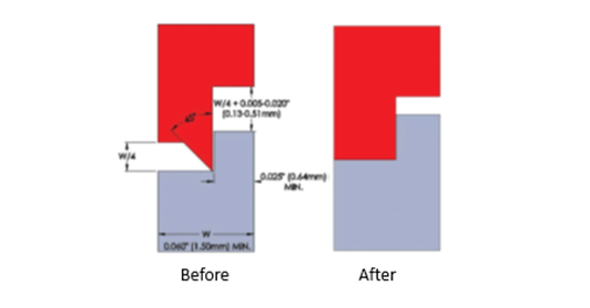
A variation of the step joint, by putting the energy director along the mating wall this enables welding of thinner sections.
Considerations for using energy directors
Smaller initial contact area reduces the energy needed, so only put energy directors where needed. The exception is when a hermetic seal is needed, in which case an energy director is needed on all of the mating surface.
Parts must be aligned before welding. Step or tongue and groove joints can be useful for this.
Shear Joint Considerations
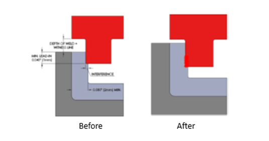
Shear joints require side walls with an interference and their strength is proportional to vertical direction of overlap. They work better for regular/symmetrical parts than those with irregular shapes.
Design for the Process
For many plastic assemblies sonic welding is a better joining method than fasteners or adhesives. It produces a strong joint while avoiding any mess or additional components. The key to successful sonic welding is appropriate material selection and part design. Use these plastic part design guidelines as a starting point, but don’t hesitate to ask a specialist for more detailed advice.